
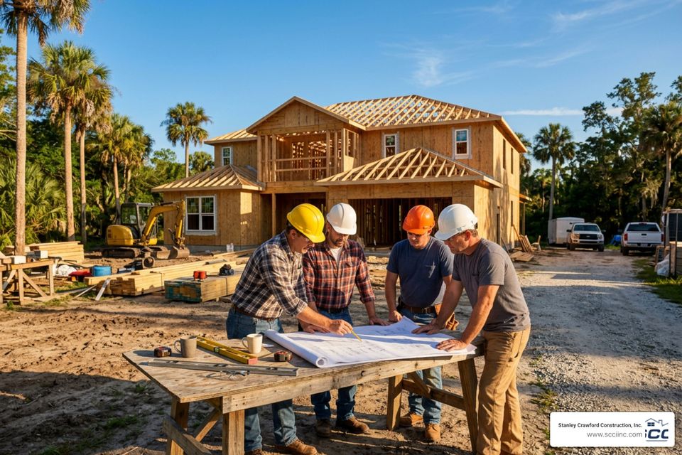
From Lines to Layouts: A Guide to Design Drawings in Construction
What Architectural Construction Drawings Actually Are (And Why They Matter for Your Custom Home)
Architectural construction drawings are the complete set of technical documents that tell a builder exactly how to construct your home — from the foundation to the roof line.
If you're planning a custom home in North Central Florida, here's the quick answer:
What are architectural construction drawings?
- A coordinated package of drawings (floor plans, elevations, sections, details) that describe every part of a building
- Used to secure building permits, coordinate trades, and guide construction from start to finish
- Produced by licensed architects and engineers, and reviewed by Florida building departments before a single shovel hits the ground
- They serve as legal contract documents between the owner, builder, and contractors
- After construction, they are updated to create "as-built" drawings that record what was actually built
These drawings are not the same as pretty design sketches. They are the instruction manual for your home.
There's an old saying in the industry: it's far better to solve a problem on paper than to discover it when workers are standing on-site waiting for an answer. A well-prepared drawing set keeps every decision — every wall thickness, every window placement, every flashing detail — resolved before construction begins. That means fewer surprises, fewer change orders, and a smoother build from start to finish.
For homeowners in High Springs, Alachua, Gainesville, Newberry, and the Town of Tioga, understanding what goes into these documents helps you ask better questions, make smarter decisions, and partner more effectively with your builder.
What Are Architectural Construction Drawings?
To understand how a house transitions from an idea in your head to a physical structure on a lot in Gainesville or Alachua, it helps to distinguish between conceptual drawings and actual architectural construction drawings.An architectural drawing in the early phases of a project is all about design intent. It shows the general layout, the look of the front facade, and how rooms connect. It is a tool for visualization and discussion.
However, once we move into the actual building phase, we need technical execution. That is where architectural construction drawings (often called the "working drawings" or "construction documents") come in.
These are highly detailed, scaled, and annotated plans that leave no room for interpretation. They are legally binding contract documents that form the basis of our agreement with you and our subcontractors. They ensure that every component complies with the stringent Florida Building Code, particularly regarding structural integrity and wind load resistance.
FeatureConceptual Architectural DrawingsTechnical Construction DrawingsPrimary PurposeEstablish design intent, spatial flow, and aesthetic style.Provide precise technical instructions for building and permitting.
Target AudienceHomeowners, developers, and design review boards.Builders, subcontractors, building inspectors, and fabricators.
Level of DetailHigh-level room layouts, basic dimensions, and 3D renderings.Exact dimensions, material specifications, wall assemblies, and schedules.
Legal StatusTypically not legally binding; used for initial approvals.Legally binding contract documents and official permit records.
Code ComplianceShows general layout without detailed code engineering.Fully engineered to meet the Florida Building Code and local regulations.
When you are ready to build, choosing a partner who understands how to translate these complex pages into a physical home is critical. To learn more about selecting the right team, read our guide on Beyond Blueprints How to Choose an Architectural Home Builder That Gets You.
The Anatomy of a Blueprint Set: Key Types of Drawings
A complete set of construction drawings is a massive, coordinated package of information. For a typical custom home in North Central Florida, this set is regularly dozens of pages long. In fact, a typical residential project can range from a 25-page set on smaller sheets up to a highly detailed 42-page set of large ARCH E (36" x 48") sheets.To keep this vast amount of information organized, the set is broken down into specific drawing types, each serving a unique purpose.
- Site Plans: These show the entire property from a bird's-eye view. A site plan indicates the exact placement of your home relative to property lines, local setbacks, and easements. It also maps out driveways, walkways, utility connection points, and grading. Under Florida standards, the "building" scope typically extends 5 feet from the structure's perimeter, and the site plan clearly delineates where utilities transition—such as waste piping at the cleanout or water lines at the main valve.
- Structural Drawings: Created in coordination with a structural engineer, these drawings detail the load-bearing elements of your home, including the concrete slab, footings, framing members, and roof trusses. In our region, these drawings are vital for proving your home can withstand local hurricane-force wind loads.
- MEP Systems: These sheets map out the mechanical (HVAC ductwork and equipment), electrical (outlets, panels, and lighting grids), and plumbing (supply and waste lines) systems, ensuring they do not physically clash with the structural framing of your home.
Floor Plans: The Foundation of Architectural Construction Drawings
The floor plan is the heart of any drawing set. Technically speaking, a floor plan is a horizontal section view taken 42 to 48 inches (about 4 feet) above the floor level, looking straight down. This specific cut height is standardized so that the drawing captures windows, doors, and wall thicknesses accurately.For a custom build in High Springs or Alachua, the floor plan is where we map out your daily life. It shows the exact thickness of interior and exterior walls, the precise locations of windows and doors, and the overall flow between spaces. When reviewing these plans, look closely at the door swings—standardized drafting rules represent side-hung doors at a 90-degree angle with an arc to show the swing path, helping you visualize clearances and furniture placement.
To dive deeper into planning your layout, check out A Comprehensive Guide to Custom Floor Plans.
Elevations and Sections: Visualizing Vertical Space
While floor plans handle the horizontal layout, elevations and sections handle the vertical dimension.- Exterior Elevations: These are flat, 2D views of the outside of your home, labeled by the compass direction they face (e.g., North Elevation, South Elevation). They show the finished floor levels, window heights, roof pitches, and exterior material transitions (such as siding, brick, or stucco).
- Cross-Sections: Imagine slicing your house in half with a giant saw and looking at it from the side. That is a cross-section. It is incredibly important because it reveals the hidden assembly of your home—how the foundation connects to the walls, how the walls connect to the roof trusses, and where the insulation layers sit. In Gainesville, where summer humidity and heat are intense, these sections are critical for verifying continuous thermal boundaries and proper moisture barriers.
Detail Drawings: The Fine Points of Architectural Construction Drawings
Detail drawings are large-scale close-ups of specific, complex junctions within the building. While a floor plan might be drawn at a 1/4" = 1'-0" scale, a detail drawing is often drawn at a much larger scale, such as 1:10, 1:5, or even full size.These drawings are where the real craftsmanship of a custom home is defined. For a home in Newberry or the Town of Tioga, we rely on detail drawings to execute:
- Flashing Details: Specifying exactly how waterproof barriers overlap around windows, doors, and roof valleys to prevent water intrusion during Florida's heavy summer downpours.
- Staircase Dimensions: Stairs are notoriously complex. Detail drawings map out the exact rise, run, handrail heights, and structural attachments.
- Custom Cabinetry and Casework: Detailing the precise measurements and construction of built-in shelving, kitchen islands, and bathroom vanities.
To ensure consistency across the industry, these visual representations follow strict international standards, such as those outlined in ISO 7519:2024, which dictate how lines, hatches, and symbols must be drawn to prevent miscommunication on the job site.
Organization, Standards, and the Uniform Drawing System
With hundreds of individual details, notes, and dimensions scattered across a drawing set, architects rely on a highly structured organizational standard called the Uniform Drawing System (UDS), which is part of the US National CAD Standard. This keeps the drawings predictable, so a builder in Lake City can open a set drafted in Gainesville and immediately find any detail.Every sheet in a professional construction set is organized using a standardized numbering system. The sheet number is typically broken down into three parts: the discipline designator, the drawing type, and the sequence number.
Discipline Designator (Letter): Tells you which trade or field the sheet belongs to.
- A: Architectural
- S: Structural
- C: Civil (site work, grading)
- M: Mechanical (HVAC)
- E: Electrical
- P: Plumbing
Drawing Type (Digit): Identifies the type of view shown on the sheet.
- 0: General (legends, symbols, general notes)
- 1: Plans (floor plans, site plans)
- 2: Elevations (exterior and interior views)
- 3: Sections (cross-sections through the building)
- 4: Large Scale Drawings (scaled-up plans or elevations)
- 5: Details (close-up construction details)
- 6: Schedules and Diagrams (window, door, and finish schedules)
Sequence Number (Two Digits): A sequential number starting at 01 (e.g., A101 is the first floor plan sheet, while A102 would be the second floor plan).
Historically, these drawings were hand-drafted with ink on vellum or tracing paper. Today, the industry has evolved to Computer-Aided Design (CAD) and 3D Building Information Modeling (BIM). BIM software allows us to build a virtual 3D model of your home first.
The 2D sheets—the floor plans, elevations, and sections—are then generated directly from this model. If we change a window location in the 3D model, it automatically updates on every single sheet in the set, drastically reducing drafting errors.
These drawings are typically plotted on standard architectural paper sizes:
- ARCH C: 18 x 24 inches
- ARCH D: 24 x 36 inches (the most common size for job sites)
- ARCH E: 36 x 48 inches (used for highly detailed or large-scale custom estates)
For a deeper look into how to read and manage these technical files, explore our resources on Navigating the World of Custom Home Blueprints Recommendations and Resources.
The Role of Drawings in the Florida Custom Home Build Process
From the moment you decide to build a custom home in North Central Florida to the day we hand over the keys, architectural construction drawings are the thread that ties the entire process together.Here is how the lifecycle of these drawings unfolds during a real-world build:
- Zoning and Permitting: Before we can break ground in cities like Gainesville or Alachua, we must submit a "permit set" of drawings to the local building department. Building officials review these plans to verify compliance with local zoning laws (setbacks, height limits) and the Florida Building Code (wind load engineering, energy efficiency). No construction can legally begin until these plans are formally approved and stamped.
- Subcontractor Coordination: Once we have the permit, the drawings become our primary communication tool on-site. We share specific sheets with our trade partners—such as sending the electrical plans (E-sheets) to our electrician or the plumbing plans (P-sheets) to our plumber. This ensures everyone is working from the exact same layout.
- Shop Drawings: For highly specialized components, like pre-engineered wood floor trusses or custom steel stair railings, the manufacturer will produce "shop drawings." These are fabrication-level plans that we, as the builder, must review and approve against the main architectural set before the components are manufactured.
- As-Built Documentation: During construction, minor adjustments are occasionally made in the field due to unexpected site conditions. We mark these changes in red ink on our master set of plans. At the end of the project, these "redlines" are digitized to create as-built drawings. These provide you with an incredibly valuable, 100% accurate record of how your home was actually built, which is useful for any future remodeling, landscaping, or maintenance.
To understand how this documentation fits into the broader timeline of your project, read our complete guide on the Custom Home Build Process From Blueprints to Better Living.
Frequently Asked Questions about Architectural Construction Drawings
What is the difference between a permit set and a construction set?
A permit set is a subset of the drawing package submitted to the local building department to secure zoning and building approvals. It contains all the critical information required to prove code compliance, such as structural engineering, life safety features, and energy calculations.A construction set is the final, fully detailed set used by our team and subcontractors in the field. It includes everything in the permit set, plus highly detailed interior elevations, finish schedules, cabinet details, and specific trim details that are not required for code approval but are essential for executing the high-end craftsmanship of your custom home.
Why is the disclaimer "Do not scale off dimensions" on blueprints?
You will find this warning on almost every professional architectural drawing. It means you should never use a physical scale ruler to measure a distance directly off a printed sheet of paper.Paper can shrink or expand slightly depending on humidity and temperature, and copying or printing machines can introduce minor scaling distortions. Even a tiny 1/16th-inch printing error can translate into several inches or feet of error on an actual job site. Builders must always rely on the written, "figured" dimensions printed on the page. If a dimension is missing, we verify it directly with the architect rather than guessing with a ruler.